Aan- of uitzetten van de ventilatie is niet meer nodig
Deze schakeling beschrijft hoe je de ventilator automatisch kunt laten in- en uitschakelen, afhankelijk van de luchtvochtigheidsgraad. Zakt deze onder een zekere drempelwaarde, aangeduid met led lampjes, dan schakelt de ventilator zich uit. Zie details voor het schakelschema in de onderstaande afbeelding. De toelichting is per onderdeel van de schakeling beschreven in het Engels).
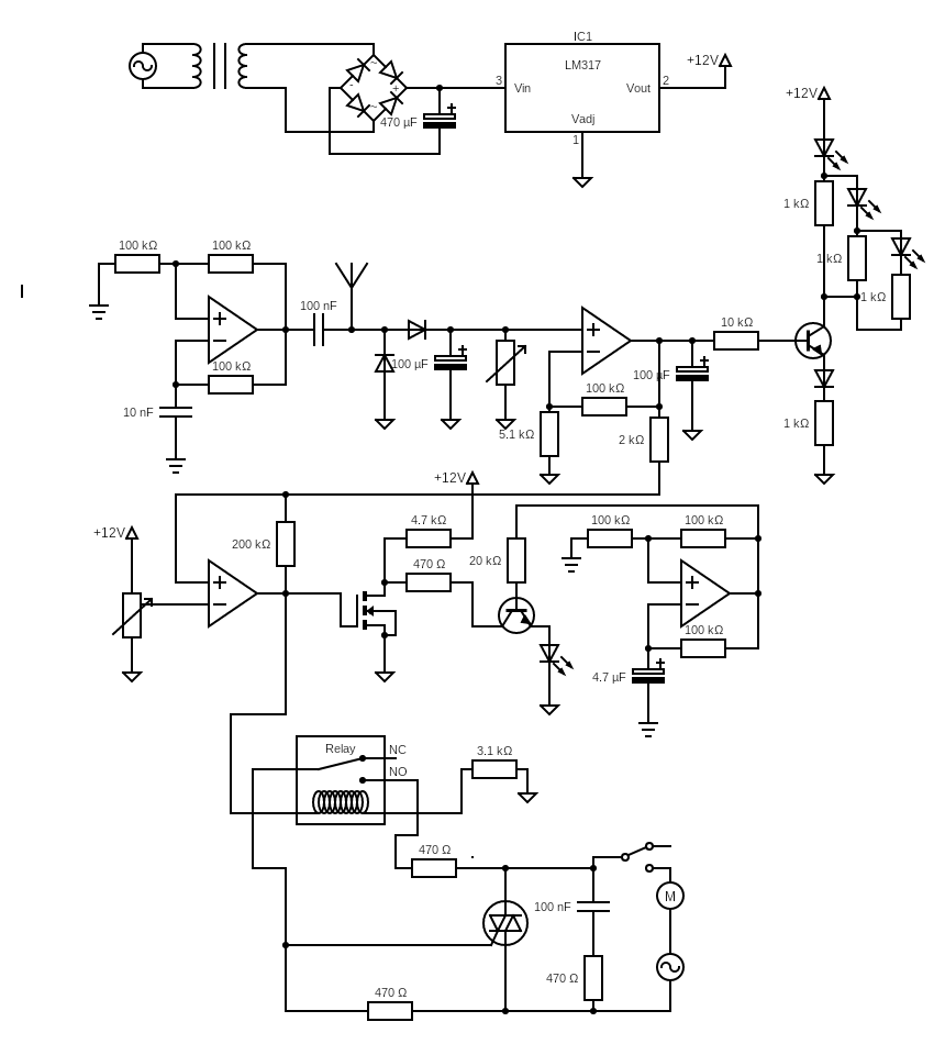
Werking
– Het doel van dit circuit is om een ventilatiemotor aan of uit te zetten bij hoge of lage luchtvochtigheid. Het betreft de ventilatie in de mechanische ventilatiekast van de woning.
– De spanning voor het circuit is 12V door middel van een transformator, gelijkrichter, afvlakcondensator en een spanningsregelaar type 7812.
– De vochtigheidssensor is van condensatorachtige aard. Bij hogere luchtvochtigheid neemt de impedantie af. Voor de meting is een wisselspanning nodig. Deze wordt in de opamp gegenereerd door middel van een relaxatie-oscillator.
– Deze relaxatie-oscillator wordt gegenereerd door een JFET opamp (LF347). Het schema bevat een beschrijving van de werking van de oscillator. De massa voor het oscilleren wordt tot stand gebracht halverwege tussen Vcc (12V) en Vdd (0V). De frequentie is ongeveer 4,5 kHz.
– Via een koppelcondensator wordt deze puls naar de vochtigheidssensor gevoerd. Na de sensor wordt het signaal gelijkgericht en na een afvlakcondensator wordt het signaal naar een versterkende opamp gevoerd. De spanning bij normale vochtigheid is ongeveer 200 mV (bij de niet-inverterende ingang van de opamp).
– Deze opamp is een CMOS opamp (CA3040) omdat dit type opamp een common mode-ingangsspanning van 0 V kan meten. In tegenstelling tot de JFET opamp, die alleen gevoelig is vanaf ongeveer 1 V. De versterking op basis van dit niet-inverterende circuit is 1+20=21 met behulp van 5,1 k en 100 k weerstanden. Het uitgangssignaal is gemiddeld ongeveer 4 tot 4,5 V, natuurlijk afhankelijk van de vochtigheid (in de badkamer).
– Het uitgangssignaal wordt gevoed in de basis van een transistor met een set LED’s aan de collectorzijde die, geactiveerd door de hoeveelheid stroom in de transistor, achtereenvolgens groen, geel en rood oplichten. Aan de emitterzijde bevindt zich een diode (om een bepaalde hoeveelheid spanningsval te bieden) en een weerstand. Bovendien heeft elke LED ook een stroombegrenzende weerstand van 1 k.
– Ten tweede wordt het uitgangsvochtigheidssignaal naar een JFET-opamp (LF347) gevoerd die de versterkte spanning bij de niet-inverterende ingang vergelijkt met een referentiespanning van een 2V variabele weerstand bij de inverterende ingang. Bij een lagere spanning < 2V bij de niet-inverterende ingang ‘wint’ de inverterende ingang en gaat de uitgang van de opamp dienovereenkomstig naar laag. In het geval van de JFET-opamp is dit vergelijkbaar met 1,2V.
– Deze uitgang wordt vervolgens aangeboden aan een C-kanaal MOSFET (RFP70N06) met een gate-sourcedrempel van 2V. Bij een lage spanning bij de gate blokkeert de MOSFET. Dit zorgt ervoor dat de spanning aan de drainzijde stijgt tot Vcc.
– Deze positieve spanning wordt aan de drainzijde afgetapt en naar een NPN-transistor geleid.
– Aan de basis van de NPN-transistor is er een continue puls met een frequentie van ongeveer 8 Hz. Deze frequentie wordt gegenereerd door middel van een relaxatie-oscillator van een JFET opamp (LF347). Op dezelfde manier als in het eerder beschreven relaxatie-oscillatorcircuit. Hierdoor gaat een blauwe LED op de emitter van de transistor knipperen. Let op: hoe hoger de spanning op de basis, hoe hoger de stroom door de emitter.
– Daarnaast wordt de uitgang van de comparator naar een optocoupler MOC serie 3063 geleid (in het schema weergegeven als een relais). De interne fototriac schakelt in bij input hoog. Omdat het 230V-circuit een inductieve belasting heeft (wisselstroommotor), ontstaan er pieken in de stroom wanneer de motor plotseling uitvalt. De optocoupler kan deze plotselinge toename in stroom niet verwerken en gaat kapot. Om dit te voorkomen, worden de uitgangen via een 470 Ohm-weerstand aangesloten op de aansluitingen MT1 en MT2 van de triac. Verder wordt de gate van de triac aangesloten op een van de uitgangen van de optocoupler. Hierdoor kan een grotere piekstroom in de triac worden verwerkt. Een snuffercircuit is parallel aan de triac geïnstalleerd door een serieweerstand (470 Ohm) en een condensator (100 nF, nominaal 600V). De triac is hiervoor ontworpen, niet de optocoupler.
– De 12V-voeding is gebouwd met een 7812-spanningsregelaar.
Leermomenten
– Soldeer niet aan de vochtsensor. Deze kan slechts 60 C° verdragen.
– Hoe hoger de spanning tussen basis en emitter, hoe hoger de stroom door basis en emitter. Afhankelijk van de bètaversterking van de transistor wordt de collectorstroom verhoogd. Weerstanden in de lijncollector en emitter bepalen alleen of de stroom lager is dan de transistor toestaat, maar de transistor bepaalt de maximaal toegestane collectorstroom.
– Een 555-timer of een opamp kan beide worden gebruikt om een blokspanning (oscillator) te genereren. Een 555-timer is hiervoor ingesteld; een opamp kan hiervoor worden gebruikt. In mijn geval wilde ik zoveel mogelijk uit de quad opamp halen.
– Quad opamps hebben het voordeel dat je een opamp vier keer op een chip kunt gebruiken. Je kunt echter geen bias of offset regelen omdat deze pin-ins ontbreken.
–Gebruik een CMOS opamp in plaats van een JFET opamp. Dan kun je met lagere input spanningen werken. De datasheet van een klassieke LM741 opamp met BJT transistors geeft een Input Voltage Range op +-13V bij typisch gebruik uitgaande van een voedingsspanning van +- 15V. Dit is de zogenaamde input common mode voltage. Daarom heb ik een aparte CMOS opamp gebruikt om met lagere input spanningen te kunnen werken.
– De MOSFET transistor blokkeert het kanaal volledig of opent het volledig. Handig om Vcc of Vdd in te stellen.
– Versterking via een inverterend of niet-inverterend circuit is transparant en eenvoudig te berekenen. Toename kan natuurlijk alleen plaatsvinden tot het niveau van Vcc.
– Let goed op het vermogen in de transistoren, chips of spanningsregelaars.
– Plaats geen diode in lijn tussen emitter output en nul rail spanning. Wanneer de stroom te laag is, schakelt de diode uit, net als de transistor, waardoor het input signaal naar de basis geen referentiepunt heeft: de input begint te zweven. Wanneer dit input signaal ook wordt gebruikt om te vergelijken met een referentie spanning op een opamp, kan de output van de opamp onvoorspelbaar worden.
Translated with www.DeepL.com/Translator